[incremental] [absolute] [tachometer] [absolute 4...20mA] [intrinsically safe questions]
1. With what serial communication is the encoder compatible?
RS232, RS422 and RS485
2. What is the maximum pulses per revolution on each encoder?
The information can be found on the data sheets, just scroll down on the Resolution field till you hit the last number. Usually limited by output frequency, as follows: F = rounds per second * resolution. Some of our encoders can go up to 150 kHz, different for each encoder.
3. What is the maximum rpm (speed) of the encoder?
The speeds vary for each encoder, the information can be found on the data sheets under 'technical data.'
4. What material is the shaft made of?
Aluminium or Stainless Steel for the hollow shafts, and stainless steel for the solid shafts.
5. What are the encoders made of?
Aluminium, Stainless Steel or Die Cast Zinc Alloy, depending on which one. It is under the 'technical data' on each data sheet.
6. What does the output mean:
|
Regular Incremental |
|
|
|
In this diagram, there are 6 outputs. A, B and O and their inverses. The signals coming out can be specified, such as A and A inv only, usually however, all six are used. Each square in the signal is one pulse, this is when light goes through the clear part of the disk. B is always 90 degrees ahead of A. (In North America and Mainland Europe, A leads B) The O is the marker pulse. Each time it goes by, it means one full turn of the encoder. |
|
4...20 mA Incremental |
|
|
|
The 4...20 mA circuit is intrinsically safe and has channels A and B. Each channel is powered by the current loop system of the 4...20mA circuits. So channel A has +A and -A, channel B has +B and -B.
They hook up as follows: + loop to 24V on the PLC and the - loop to one of the inputs on the PLC. |
|
DIN 19234 Incremental |
|
|
|
This is the industry standard intrinsically safe electronics (NAMUR). This is always hooked up to an isolator. This circuit is made for the IS and hazardous area markets. It has a current output. |


7. What is a "gated marker"?
A gated marker is a marker pulse (see above explanation of regular incremental output) which is gated to channel A or B or A+B. Basically, the marker pulse is set to the highs of the regular channels. The diagrams below show what it should be like:


8. What do the IP ratings mean?
Click here for a full list of certifications.
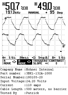
9. How long can the cable be before the signals go haywire?
Hundred meters is pushing it. Depends on outside noise also.
Here are actual waveforms from a long cable test we did at Hohner UK
(we used 500 meters of cable, outdoors) That's 1/2 kilometer of cable
Test at 9.6V (signal breaks down)
10. If I want a longer cable, can I do something to make it work?
Follow these simple steps, in this order:
a) Lower the voltage until it works. Try 15V, then 10V, then 6V, then 5V.
b) Still no good? Try lowering the voltage and put a 300 ohm "pull up" resistor with the output channel. So on the black wire on the cable or GND pin on the connector, attach the above resistor in parellel to the output cannel, as seem in the diagram (click here to see diagram of before and after connections). This works for most cases. If you have a high frequency output, (high resolution and rpm), then lower the voltage to about 5 V and lower the pull up resistor value accordingly. If this still does not work, then you need a differential amplifier (RS485) in between the encoder and the PLC. This is for extreme cases only, such as 200 or more meters of cable.
c) Hohner is developing a "black box" which goes between your system and the encoder which improves the signal in long cable runs.
11. The encoder is not working, what is wrong?
Troubleshooting the encoder:
a) Ground and Positive is hooked up properly
b) Channel O is NOT the output, its the marker pulse. A is the primary output
c) Ground and Positive have to come and go the same same source as the outputs. You can not power the encoder from an independent source and have the output go somewhere completely different.
d) Supply between 5 and 24 Volts. It will work up to 30V.
e) It is very cold. Our encoders are specified to -20 degrees C, -40 is available upon request.
f) For a current loop, hook it up as follows: Red goes +24 Volts on the PLC and the black goes to an input on the PLC, NOT a ground.
g) The encoders made in the UK have channel B leading channel A by 90 degrees. If you are replacing a North American or European encoder with one of ours, swap over channel A and B, as theirs have channel A leading B by 90 degrees.
h) DO NOT put 24V to the output channels, you will not get any signals, all you will get is a burnt output chip. Click here to see the consequences of putting 24 Volts to an output channel.
1. What is an absolute encoder?
As with an incremental encoder, it measures position. It will 'remember' its position after a power failure. In other words, it sees the position as an absolute value. The disc has a total of 4096 distinct positions. Each with a different value.
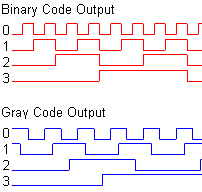
2. What output do I get?
You get a binary or gray word. As in the diagram below.
3. What does it mean to have a single turn absolute encoder?
A single turn encoder give you an absolute value within 360 degrees, but will not give you any data on how many turns it has made. This means that you have a total of 4096 distinct positions within those 360 degrees, each position is a binary or grey code word.
3. So what is a multi-turn encoder?
A multi turn encoder give you an absolute value within 4096 turns. This means that within 4096 turns of the encoder shaft, you will know in which turn you are and where within this turn. For instance, you will know that you have gone 31 turns, and that you are 3567 counts (of a total of 4096 per turn) within this turn. There are 4096 x 4096 distinct positions (16777216 positions). So if there is a power failure, you will know exactly where you are, very precisely, when the power is turned back one, even if the encoder has turned.
1. What is a tachometer?
A tachometer measures the speed of rotation. Same as with the tachometer in the car
2. What output do I get?
Our tachometers have a 4...20 mA output. As in the diagram below, the minimum rpm (usually 0) will give an output of 4mA. And the maximum rpm will give an output of 20 mA. The maximum rpm is specified by the customer. Usually we have 300, 1000 and 3000. Anything in between is available.

3. Where would I use one of these?
The electronics we developed for this are specific to hazardous areas, hence the 4...20mA circuit. Applications which we have sold this to are for data logging and wire line measurement in the oil and gas industry. Simply measures the rpm of the rotating shaft.
1. What is a position sensor?
A position sensor is what we call an absolute encoder with a 4...20mA output.
2. So what does the output look like?
See the diagram below. It goes like this: At 0 degrees, you get 4 mA and at 359 degrees you get 20 mA. Everything else is linearly in between. The circuit uses a digital to analogue converter.

3. Can this be multi turn also?
Yes it can, the diagram above is for a single turn output. The multi turn output is the same, with the difference being that you get 20 mA at the max number of turns. For instance, at 0 degrees and 0 turns you get 4 mA. And at 359 degrees and 31 turns (32 turns, 31 + 359 degrees) you get 20 mA.

4. What is the resolution per 4...20 mA ramp?
Basically this is identical to a parallel output encoder, only difference is that it has an extra board with a Digital to Analogue converter to get you the 4...20 mA ramp. For our intrinsically safe version, we use 10 bits per ramp (1024 points per ramp). Our non-intrinsically safe version has 12 bits per ramp (4096 points per ramp).
5. If this is always 4...20mA, won't the precision go down with a higher number of turns?
Correct, this is why we limit the number of turns to a maximum of 64 turns. You can get a higher number of turns, but the resolution will not be very good. So for the intrinsically safe 10 bit version, you get 1024 points for whatever number of turns you have. So in theory, you can have 1024 turns, but you only get one point per turn, which is a very poor resolution.
1. Why would I buy an intrinsically safe encoder?
An intrinsically safe encoder is used in applications where there is a risk of some hazard or other. For instance if there are gasoline fumes, fine saw dust, chemicals and other combustible substances around the encoder. In other words, if there is a short circuit in the encoder, or a power spike coming to the encoder, the encoder will NOT emit a spark, and thus your system will not go up in flames.
2. So this means that if I want to use an encoder in an oil refinery, I simply get an intrinsically safe version?
That is the first step, yes. But, you DO NEED A BARRIER or ISOLATOR. Without a barrier/isolator, it defeats the whole purpose. Or you get an explosion proof encoder, described below.
3. What is a barrier or isolator?
A barrier is a device which safeguards the sensor from spikes in power and short circuits. A barrier has to be grounded. The protection is usually with a zener diode and there is a safety fuse. A power spike or short circuit causes the fuse to blow, so the "harmful" electricity does not reach the sensor, so your system does not go up in flames. The barrier has to be in the "safe zone" of the system while the sensor is in the "hazardous zone".
An Isolator has the same function, but the signals are galvanically isolated. It does not need grounding. It's easier to install, and one does not have to worry about poor grounding, and are generally more reliable. In a desert for instance, it is difficult to get a proper ground, so an isolator is preferred. The isolator also has to be situated in the "safe zone" while the sensor is in the "hazardous zone".
Recommendations when using a barrier/isolator: You need a good power supply and a good ground. If you do not, you risk the chance of 'making the barrier/isolator do its job', which is to 'blow up' instead of the encoder blowing up. To much power or a poor ground can cause the barrier/isolator to 'blow' instead of the device on the hazardous side. If the barrier continuously blows, then please check your power supply and ground, something is a miss in your system, since if it were not for the barrier/isolator, the sensor would spark and your factory could go up in flames.
4. Where can I buy these devices?
We manufacture EEx ia IIB barriers for our regular incremental voltage encoders. They can be bought from us.
It has ATEX approval and mounts to industry standard DIN rails EN 50 022 (35mm X 7.5mm). It has indicator lights for the channels. No other company makes a six channel barrier as far we are aware.
For Barriers and Isolators for our 4...20mA electronics and Namur electronics, we recommend you use MTL products. These can be bought from us, in good practice, we charge the MTL list prices.
Click here for list of isolators and barriers suitable for our encoders and the prices for them
5. How do I use the devices?
The barrier/isolator has to be connected as per the data sheet instructions: data sheets
For the Hohner barriers: All channels have to go into the barrier, even if you do not intend to use them. It will not work otherwise. If you really insist on not feeding all the channels from the encoder to the barrier, then you have to put the ground to the complementary channels. On the output of the barrier, you can use any channel you want, they do not have to be connected.
Do not use these Hohner or MTL barriers/isolators with our EEx d IIC rated encoder. These encoders (DXE, 31, MXE and RXE series) are Flame Proof and do not require a barrier. It is a waste of money to get a barrier for these.
6. How safe is this "intrinsically safe" stuff then?
Our encoders are rated to EEx ia IIB and EEx ia IIC. Our barrier is rated to EEx ia IIB, for the IIC stuff, we recommend MTL isolators which are rated to EEx ia IIC. This means all the above can be used in Zone 0.
7. What is the difference between the IIB and the IIC categories?
Both are "zone 0". The "B" and "C" part of the code covers the gas groups where they are safe to use. IIC is rated for more explosive gases than IIB. Industry standard is IIB, our 4...20mA and Namur electronics are IIC, as these are low current devices and usually used offshore and in mining applications.
8. And what is Zone 0?
Oh sorry, well there are three main zones in the hazardous areas. Gasoline station example:
Zone 0 - Safe to use the encoder inside the cars gasoline tank.
Zone 1 - Safe to use by the opening of the cars gasoline tank, where the nozzle goes.
Zone 2 - Safe to use by the gasoline pump (outside of it)
9. What if I do not want to use a barrier, do I have other options?
Yes, you can get a Flame Proof encoder, these are rated to EEx d IIC. Which means that the housing has a flame quench path. So a spark will not get out of the housing. This works up to Zone 1.
10. So I am better off getting a Flame Proof encoder, since it will be cheaper than and encoder and barrier?
Depends, Flame Proof encoders are quite pricey, they are made of stainless steel or aluminium and weigh a ton. So the price is about the same. But if you do not wish to fuss with barriers and isolators, it's the best choice. Its simply plug+play as a regular encoder. The other advantage is that any type electronics can be inside the enclosure. There are no max voltage and max current to worry about (at least not for encoders, since it will never be more than 40V and maybe 200mA)