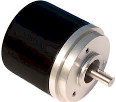
Series CM24 multi-turn absolute shaft encoder with parallel output
(new style part number)
|
hohner |
Hohner Automation Ltd. |
| Home | Distributors | Terms | About Us | Accessories | Download 3D AutoCAD |
|
Series CM24 multi-turn absolute shaft encoder with parallel output (new style part number)
|
| 2 | 4 | X | X | - | X | X | X | X | - | 4 | 0 | 9 | 6 | |||||||||
|
|
||||||||||||||||||||||
| XX |
Shaft Size |
XX | Output Circuit |
R E S O L U T I O N |
||||||||||||||||||
|
K1 = 12 x 25 mm |
Extended Line Driver: |
4096 = 12 x 12 bit |
||||||||||||||||||||
| 23 = Binary (cw / ccw) | ||||||||||||||||||||||
| 26 = Gray (cw / ccw) | ||||||||||||||||||||||
| X | Connection | X | Connection Exit | |||||||||||||||||||
| 1 = 2 m cable | A = Axial | |||||||||||||||||||||
| 2 = 5 m cable | R = Radial | |||||||||||||||||||||
| J = 9516, 16 pin plug & socket | ||||||||||||||||||||||
| K = 9526, 26 pin plug & socket | (Stainless Steel will be issued as a "special product") | |||||||||||||||||||||
| If using the 26 pin connector, cw/ccw selectability is only possible if the resolution is less or equal to 12 x 11 bits (23 bits) | ||||||||||||||||||||||
| Technical Data | Connection Options | |||||
| Operating temp: | - 20 ...+ 60 degrees C | Bin / Gray | 26 pole | Cable | Detail | |
| - 4 ...+ 140 degrees F | PS GND | 1 | Black | positions / turn | ||
| On request: | -20 ... + 100 degrees C | PS 12...24 V | 2 | Red | ||
| Power supply: | 11 - 24V | 2-0 (LSB) | 3 | White | 4096 | |
| Current consumption: | 220 mA (max.) | 2-1 | 4 | Blue | 2048 | |
| Line driver output max: | 50 mA per channel | 2-2 | 5 | Yellow | 1024 | |
| Weight: | 4 kg Stainless Steel | 2-3 | 6 | Green | 512 | |
| 1.5 kg Aluminum | 2-4 | 7 | Violet | 256 | ||
| Protection: | IP 65 (IP54 available) | 2-5 | 8 | Brown | 128 | |
| Housing: | Aluminum or SS | 2-6 | 9 | Pink | 64 | |
| Shaft: | Stainless Steel | 2-7 | 10 | Turquoise | 32 | |
| Bearings: | 2 x 6001 ZZ C2 | 2-8 | 11 | Gray | 16 | |
| Torque: | 0.4 oz/in (3 N-cm) | 2-9 | 12 | Orange | 8 | |
| Shaft Seal: | Nitrile Double Lip | 2-10 | 13 | Green/Red | 4 | |
| Humidity: | Up to 98% permissible | 2-11 (MSB) | 14 | Green/Blue | 2 | |
| Speed: | 3000 RPM max. | Multiturn Section | total # of turns | |||
| Shock: | 10g (6msec) | 2-12 (LSB) | 15 | Yellow/Red | 2 | |
| Vibration: | 5g (500 Hz) | 2-13 | 16 | White/Red | 4 | |
| Shaft load: | Radial max 10 lbs | 2-14 | 17 | Yellow/Blue | 8 | |
| 2-15 | 18 | White/Blue | 16 | |||
| Output | 2-16 | 19 | Blue/Black | 32 | ||
 |
2-17 | 20 | Orange/Blue | 64 | ||
| 2-18 | 21 | White/Green | 128 | |||
| 2-19 | 22 | Orange/Green | 256 | |||
| 2-20 | 23 | Green/Black | 512 | |||
| 2-21 | 24 | Yellow/Violet | 1024 | |||
| 2-22 | 25 | Yellow/Brown | 2048 | |||
| 2-23 (MSB) | 26 | White/Brown | 4096 | |||
| cw / ccw | Black/Red | |||||
| For cw, leave Black/Red disconnected | ||||||
| For ccw, set Black/Red wire to ground. | ||||||
|
FOR BINARY ONLY: (For different resolution in gray code, specify when ordering) All our multi-turn encoders are 12 x 12 bit standard. For different resolutions, leave some of the wires disconnected as follows: Single Turn Changes: The MSB must always be wired and the LSB left unwired to adjust resolution Multi Turn Changes: The LSB must always be wired and the MSB left unwired to adjust resolution
Example: If 1024 positions / turn are required with 2048 turns in total, make the following changes:
Single Turn Section: Leave pin 3 and 4 disconnected Multi Turn Section: Leave pin 26 disconnected |
||||||
|
|
| Mounting Instructions |
| To mount
encoder on machine: Option 1 is to mount with 3 screws or, option 2
is to mount using synchroflange mounting brackets. Hook up the
encoder with the connections as described. Make sure power supply
meets specifications. Attach encoder to mounting bracket as
shown. Attach shaft using a flexible coupling.
|
| Dimensions |
|
|
| Hohner Automation Ltd. | Tel: +44 (0) 1978 363-888 |
| Whitegate Industrial Estate | Fax: +44 (0) 1978 364-586 |
| Wrexham LL13 8UG | E-mail: uksales@hohner.com |
| United Kingdom | Web: www.hohneronline.co.uk |

